ASME B18.9 TABLE 1 Standard Dimensions for Plow bolts, inch series
Plow bolts (round, countersunk, square neck)
Dimensional Drawing and Technical Diagrams
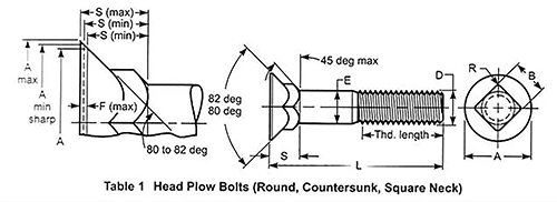
Key Dimensions and Technical Parameters
|
Dimensions in inches (1 inch=25.4 mm) sourceASME B18.9 table 1 |
|||||||||
| Publication date: 2007 | |||||||||
|
d Thread size
|
E max | E min |
A max
|
A min
|
F max | S max |
S min
|
B max
|
B min |
| Regular head | |||||||||
|
5/16
|
0.312 | 0.299 | 0.605 | 0.578 | 0.025 | 0.269 | 0.243 | 0.325 | 0.313 |
|
3/8
|
0.375 | 0.36 | 0.708 | 0.671 | 0.031 | 0.312 | 0.281 | 0.387 | 0.375 |
|
7/16
|
0.438 | 0.421 | 0.826 | 0.781 | 0.036 | 0.364 | 0.328 | 0.450 | 0.438 |
|
1/2
|
0.5 | 0.483 | 0.945 | 0.89 | 0.042 | 0.417 | 0.375 | 0.515 | 0.5 |
|
9/16
|
0.592 | 0.544 | 1.045 | 1 | 0.045 | 0.461 | 0.416 | 0.578 | 0.563 |
|
5/8
|
0.657 | 0.06 | 1.147 | 1.09 | 0.050 | 0.506 | 0.456 | 0.64 | 0.625 |
|
3/4
|
0.782 | 0.729 | 1.303 | 1.25 | 0.050 | 0.541 | 0.491 | 0.765 | 0.75 |
|
7/8
|
0.938 | 0.853 | 1.512 | 1.47 | 0.063 | 0.626 | 0.563 | 0.906 | 0.875 |
| 1 | 1.062 | 0.976 | 1.700 | 1.656 | 0.063 | 0.69 | 0.627 | 1.031 | 1 |
| Repair head | |||||||||
|
5/16
|
0.312 | 0.299 | 0.556 | 0.531 | 0.020 | 0.232 | 0.212 | 0.325 | 0.313 |
|
3/8
|
0.375 | 0.36 | 0.659 | 0.624 | 0.025 | 0.272 | 0.247 | 0.387 | 0.375 |
|
7/16
|
0.438 | 0.421 | 0.779 | 0.734 | 0.030 | 0.324 | 0.294 | 0.450 | 0.438 |
|
1/2
|
0.5 | 0.483 | 0.898 | 0.843 | 0.035 | 0.375 | 0.34 | 0.515 | 0.5 |
| 9/16 | 0.592 | 0.544 | 0.1002 | 0.953 | 0.040 | 0.423 | 0.383 | 0.578 | 0.563 |
| 5/8 | 0.657 | 0.06 | 1.096 | 1.047 | 0.040 | 0.458 | 0.418 | 0.64 | 0.625 |
| 3/4 | 0.782 | 0.729 | 1.252 | 1.203 | 0.040 | 0.493 | 0.453 | 0.765 | 0.75 |
| 7/8 | 0.938 | 0.853 | 1.465 | 1.422 | 0.050 | 0.573 | 0.523 | 0.906 | 0.875 |
| 1 | 1.062 | 0.956 | 1.653 | 1.609 | 0.050 | 0.637 | 0.587 | 1.031 | 1 |