ASME B18.8.1 Standardmäßig Abmessungen für Cotter pins, inch series
Rundkopfnieten mit Loch
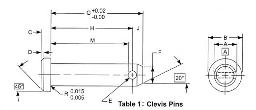
Maßzeichnungen und technische Diagramme
Wichtigste Abmessungen und technische Parameter
|
Dimensions in inches - source ASME B 18.8.1 Pubblication date:1994 |
||||||||||||||||||||||||||
| Nominal size or Basic Pin Diameter | A | B | C | D | E | F | G | H | J | M | ||||||||||||||||
| max | min | max | min | max | min | ±0.01 | max | min | max | min | nom | max | min | ref | min | |||||||||||
| 3/16 (0.188) | 0.186 | 0.181 | 0.32 | 0.30 | 0.07 | 0.05 | 0.02 | 0.088 | 0.073 | 0.15 | 0.14 | 0.58 | 0.504 | 0.484 | 0.09 | 0.440 | ||||||||||
| 1/4(0.250) | 0.248 | 0.243 | 0.38 |
0.36 |
0.10 | 0.08 | 0.03 | 0.088 | 0.073 | 0.21 | 0.20 | 0.77 | 0.692 | 0.672 | 0.09 | 0.628 | ||||||||||
| 5/16(0.312) | 0.311 | 0.306 | 0.44 | 0.42 | 0.10 | 0.08 | 0.03 | 0.119 | 0.104 | 0.26 | 0.25 | 0.94 | 0.832 | 0.812 | 0.12 | 0.752 | ||||||||||
| 3/8(0.375) | 0.373 | 0.368 | 0.51 | 0.49 | 0.13 | 0.11 | 0.03 | 0.119 | 0.104 | 0.33 | 0.32 | 1.06 | 0.958 | 0.938 | 0.12 | 0.878 | ||||||||||
| 7/6(0.438) | 0.436 | 0.431 | 0.57 | 0.55 | 0.16 | 0.14 | 0.04 | 0.119 | 0.104 | 0.39 | 0.38 | 1.19 | 1.082 | 1.062 | 0.12 | 1.002 | ||||||||||
| 1/2(0.500) | 0.496 | 0.461 | 0.63 | 0.61 | 0.16 | 0.14 | 0.04 | 0.151 | 0.136 | 0.44 | 0.43 | 1.36 | 1.223 | 1.203 | 0.15 | 1.127 | ||||||||||
| 5/8(0.625) | 0.621 | 0.616 | 0.82 | 0.80 | 0.21 | 0.19 | 0.06 | 0.151 | 0.136 | 0.56 | 0.55 | 1.61 | 1.473 | 1.453 | 0.15 | 1.337 | ||||||||||
|
3/4(0.750) |
0.746 | 0.741 | 0.94 | 0.92 | 0.26 | 0.24 | 0.07 | 0.182 | 0.167 | 0.68 | 0.67 | 1.91 | 1.739 | 1.719 | 0.18 | 1.628 | ||||||||||
| 7/8(0.875) | 0.871 | 0.866 | 1.04 | 1.02 | 0.32 | 0.30 | 0.09 | 0.182 | 0.167 | 0.80 | 0.79 | 2.16 | 1.989 | 1.969 | 0.18 | 1.878 | ||||||||||
| 1(1.000) | 0.996 | 0.991 | 1.19 | 1.17 | 0.35 | 0.33 | 0.10 | 0.182 | 0.167 | 0.93 | 0.92 | 2.41 | 2.239 | 2.219 | 0.18 | 2.128 | ||||||||||