DIN 318 Standard Dimensions for Wing screws with edeged wings (American form)
Wing screws with edeged wings (American form)
This standard DIN 318 specifies dimensions, designation and technical delivery conditions for M4 to M12 wing screws with edged wings, of product grade C and made of malleable cast iron, steel or copper-zinc alloy.
Dimensional Drawing and Technical Diagrams
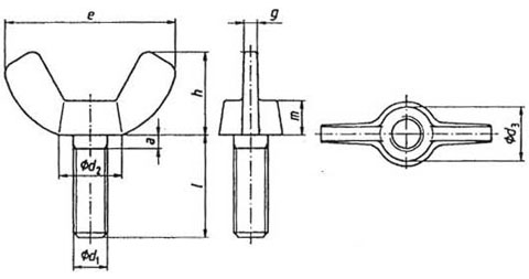
Key Dimensions and Technical Parameters
|
Dimensions in mm - source DIN 318 |
||||||
| Publication date: 07/1999 | ||||||
|
d thread size
|
M 4
|
M 5
|
M 6
|
M 8
|
M 10
|
M 12
|
|
P
|
0.7
|
0.8
|
1
|
1.25
|
1.5
|
1.75
|
|
a max
|
2.1
|
2.4
|
3
|
4
|
4.5
|
5.3
|
|
e min
|
19
|
24.5
|
29
|
35
|
47
|
63
|
|
h min
|
9
|
11
|
14
|
17
|
22
|
29
|
|
g min
|
1.1
|
1.5
|
1.5
|
2
|
3.6
|
4.1
|
|
d2 min
|
7
|
9
|
11
|
13
|
18
|
21
|
|
d3 min
|
5.5
|
7.5
|
9
|
10.5
|
14
|
17
|
|
m min
|
3.2
|
4
|
5
|
6.5
|
8
|
10
|
|
DIN 318 1999 - commercial sizes |
||||||
|
thread size
|
M4 | M5 | M6 | M8 | M10 | M12 |
| nominal length l | ||||||
| 6 | X | |||||
| 8 | X | X | X | |||
| 10 | X | X | X | X | ||
| 12 | X | X | X | X | ||
| 14 | X | X | X | X | ||
| 16 | X | X | X | X | X | X |
| 18 | X | X | X | X | X | X |
| 20 | X | X | X | X | X | X |
| 25 | X | X | X | X | X | |
| 30 | X | X | X | X | X | |
| 35 | X | X | X | X | ||
| 40 | X | X | X | X | ||
| 45 | X | X | X | |||
| 50 | X | X | X | |||
| 60 | X | |||||
|
Dimensions in mm -wing nuts commonly used on the market |
|||||||
| d thread size | M 3 | M 4 | M 5 | M 6 | M 8 | M 10 | M 12 |
|
e
|
18.5 | 22 |
22
|
26.8 |
30.3
|
35.3
|
47.5
|
|
h
|
8.8 | 10.5 |
10.5
|
12.9
|
14.8
|
17.3
|
22.3
|
| d2 | 7.8 | 9.5 |
9.5
|
11.9
|
13.5
|
15.3
|
20.5
|